Evaluation of Cancer Stem Cell Migration Using Compartmentalizing Microfluidic Devices and Live Cell Imaging
Abstract
In the last 40 years, the United States invested over 200 billion dollars on cancer research, resulting in only a 5% decrease in death rate. A major obstacle for improving patient outcomes is the poor understanding of mechanisms underlying cellular migration associated with aggressive cancer cell invasion, metastasis and therapeutic resistance1. Glioblastoma Multiforme (GBM), the most prevalent primary malignant adult brain tumor2, exemplifies this difficulty. Despite standard surgery, radiation and chemotherapies, patient median survival is only fifteen months, due to aggressive GBM infiltration into adjacent brain and rapid cancer recurrence2. The interactions of aberrant cell migratory mechanisms and the tumor microenvironment likely differentiate cancer from normal cells3. Therefore, improving therapeutic approaches for GBM require a better understanding of cancer cell migration mechanisms. Recent work suggests that a small subpopulation of cells within GBM, the brain tumor stem cell (BTSC), may be responsible for therapeutic resistance and recurrence. Mechanisms underlying BTSC migratory capacity are only starting to be characterized1,4.
Due to a limitation in visual inspection and geometrical manipulation, conventional migration assays5 are restricted to quantifying overall cell populations. In contrast, microfluidic devices permit single cell analysis because of compatibility with modern microscopy and control over micro-environment6-9.
We present a method for detailed characterization of BTSC migration using compartmentalizing microfluidic devices. These PDMS-made devices cast the tissue culture environment into three connected compartments: seeding chamber, receiving chamber and bridging microchannels. We tailored the device such that both chambers hold sufficient media to support viable BTSC for 4-5 days without media exchange. Highly mobile BTSCs initially introduced into the seeding chamber are isolated after migration though bridging microchannels to the parallel receiving chamber. This migration simulates cancer cellular spread through the interstitial spaces of the brain. The phase live images of cell morphology during migration are recorded over several days. Highly migratory BTSC can therefore be isolated, recultured, and analyzed further.
Compartmentalizing microfluidics can be a versatile platform to study the migratory behavior of BTSCs and other cancer stem cells. By combining gradient generators, fluid handling, micro-electrodes and other microfluidic modules, these devices can also be used for drug screening and disease diagnosis6. Isolation of an aggressive subpopulation of migratory cells will enable studies of underlying molecular mechanisms.
Protocol
1. BTSC's cell dissociation
BTSCs are derived from pre-existing cultures grown in serum-free stem cell medium as neurospheres. culture of which is previously described10, 11.
- Prepare cell suspension from BTSC-derived neurospheres. BTSC-derived neurospheres are collected in a 15 ml conical tube and centrifuged at 900 rpm for 5 minutes. Faster centrifugation can shear and/or damage the neurospheres. Supernatant is aspirated and neurosphere culture is resuspended in 0.5 ml of pre-warmed Accutase. This solution is incubated for 5-10 minutes at 37°C allowing the neurospheres to loosen. Cells are mechanically disrupted with 10-20 gentle strokes of a P100 pipette and then 1.5 ml of stem cell medium is added to the cells to neutralize the Accutase.
- The BTSCs are then centrifuged at 1300 rpm for 5 minutes, and resuspended in 1 ml of stem cell medium.
- A 50 μl aliquot is removed from the suspension and placed into a microcentrifuge tube for cell counting 50 μl of trypan blue is added to the Eppendorf tube and the suspension is placed in a hemocytometer for cell counting.
- If required after cell counting, additional stem cell medium is added to the BTSC suspension to give a cell density of 20,000 live cells/μl media.
2. Fabrication of bi-layered su-8 master and molding of PDMS stamp (see figure 1)
We use optical lithography and soft lithography to fabricate su-8 master and PDMS stamp, which are essential for assembly of the microfluidic devices. Slightly different than the standard procedure12, our su-8 master is composed of two layers. The 3-μm-tall microchannels are casted in the first/bottom layer earlier in the process, while the 250-μm-tall seeding and receiving chambers are in the second/upper layer. In order for correct connection between two culture compartments (microchannels and chambers), the two layers have to be accurately aligned in position. However, thickness and opacity of the second layer are large enough to block the fiducial/optical aligner from accessing the bottom features. Here we design the masks with fiducial markers being remotely positioned. Thus, these markers in the first layer can be selectively shielded while spinning the second layer. As a result, both layers of features are made in one master and ready for molding in bas-relief of the PDMS stamp.
- Design and prepare two photo-masks. One mask consists of two fiducial markers and an array of microchannels (400 μm long and 10-50 μm wide) for the first layer. Another mask consists of seeding and receiving chambers (2 mm long and 600 μm wide) for the second layer. Both masks are designed in Illustrator (Adobe, California), laser-printed onto transparency films (Thin Metal Parts, Colorado), cleaned with isopropanol and air-dried.
- Make the first layer with su-8 photoresist (MicroChem, Massachusetts) according to product manual from supplier. First, spin-coat the handle wafer (WRS Materials, California) with 3-μm-thick photoresist of su-8 (5), followed by soft-baking. The photoresist is then ultraviolet-exposed and cured with the corresponding mask in close-contact, followed by post-baking and developing.
- Spin-coat the second layer with 250 μm thick su-8 (2100). In order to prevent thick photoresist from blocking the fiducial markers from the first layer, we cover these areas with scotch tape in prior to spin-coating of the second layer. The tape is then peeled off to reveal the markers for alignment purpose.
- UV-expose the second layer with the second mask. With the alignment markers revealed, it is straightforward to align them to the ones in the second mask using optical mask aligner. The second layer of photoresist is then ultraviolet-exposed and cured in close-contact, followed by post-baking and developing.
- Anti-stick coat the resulted master. To assist in removal of cured PDMS, the su-8 master can be silanized via vapor deposition to make the surface a nonstick-type coating. Simply place it into a desiccator for at least one hour, with several drops of trichloro(1H,1H,2H,2H-perfluorooctyl)silane solution under vacuum.
- Mold PDMS with the master. Mix prepolymer base and curer of PDMS Sylgard 184 (Dow Corning, Michigan) in 10:1 ratio thoroughly. Place it in a desiccator for vacuum degassing until no air bubble is seen. Pour the mixture on the mask and degas again if new air bubble is introduced. Cure the mold on a level hotplate for 2 hours at 90 C. After it cools to room temperature, gently release the PDMS stamp. Thus, culturing channels are engraved in PDMS and ready for assembly of device. The master is reusable for molding until it is cracked or worn. The anti-stick coating needs to be performed again when the stickiness regains.
3. Assembly of microfluidic devices and cell culturing (figure 2)
In order to culture cells, feature-engraved PDMS stamp is attached to a glass coverslip to form enclosed channels. Inlets and outlets are created for loading the culture/media. Meanwhile, cleanup and other procedures to the glass substrate and PDMS stamp are necessary to ensure the cell-compatibility.
- Make reservoirs through the PDMS stamp using biopsy hole puncher. We choose their diameter to be 6 mm. These reservoirs serve for two purposes. One is to hold extra nutrient for cell growth. The other is for the access of pipette loading and vacuum aspiration.
- Soak the PDMS stamp in 70% of ethanol for 30 min and then rinse it with de-ionized water for another 10 min. The purpose is to clear potential organic residuals introduced during fabrication process, and uncrosslinked PDMS contamination. More intense and thorough cleaning processes such as organic extraction13 and Soxhlet extraction14 were used elsewhere. However, we found it unnecessary in BTSC culture.
- Sterilize the PDMS stamp using autoclave (121°C, 35 min). This step further completes the crosslink reaction of PDMS. Starting from this step and until step 3.6, all procedures are taken in sterile manner.
- The PDMS stamp is then laid on a glass coverslip, which is previously coated with poly-L-lysine.15-17 The device is then coated with laminin by filling the channel with laminin solution overnight at 37°C. Laminin is aspirated from the device and the device is washed with stem cell medium.
- Load cell suspension from step 1 into reservoirs and channels. 11 μl of dissociated cells are placed in one seeding reservoir. Vacuum aspiration is used to force cells into the seeding chamber, if necessary. An additional 7 μl of cells are placed the adjoining seeding reservoir. Note: Average cell density is 20,000 cells/μl media. After five minutes, the seeding and receiving reservoirs are flooded with media.
- Place a 0.5-1 mm pre-autoclaved PDMS sheet on top. The naturally-occurred surface adhesion between two PDMS pieces will make the cell culture sealed and ready for transport, incubation and microscopic imaging.
4. Long-term time-lapse imaging of BTSC migration with BioStation IM (Nikon Instruments Inc, Melville, USA).
Combining camera, software and incubator all in one box, this microscopic system makes it possible to image cell culture with no disturbance for days. In addition, its unique motor design moves the objective lens and keeps sample stage stationary in the point-visiting feature. This makes it practical to image parallel experiments and track cell locomotion in high-throughput assay.
- Pre-equilibrate the Biostation IM for 45 minutes to stabilize the temperature, moisture and air supply. Addition of several water-contained dishes in sample chamber is used to maintain proper humidity.
- Load the cell-contained device in the sample chamber of microscope, and center it using micro tweezers.
- Set the focus, position-points and time-points in Biostation software and start the time-lapse.
5. Representative results:
Examples of visual inspection and characterization of cancer cell migration by using a compartmentalizing microfluidic device are illustrated in Figure 3 and Figure 4. The cell-line is BTSC. With our current setup, phase images of cell culture can be continuously recorded for as long as 5 days (Figure 3) and as frequent as every 2 seconds (Figure 4). Beyond 5 days, culture media need to be replaced for nutrient replenishment and waste removed. Our long-term time-lapse identifies a revolving sequence of six cell stages during its migration based on the morphological changes. As illustrated in Figure 3, we describe them as (i) pre-migration, (ii) initiation, (iii) path-exploration, (iv) cruising, (v) destination-exloration and (vi) post-migration. In the receiving chamber, spindle-shaped cells stay in stage (i) as in bulk tumors that are able to grow, divide and gradually migrate. As they approach the microchannel entrance, a few cells proceed to stage (ii) when they expand and generate adhesive protrusion. Only one of them is able to occupy the entrance and proceed to stage (iii), which can explore the migration direction. Once the cell determines the migration direction, it proceeds to stage (iv) to cruise through the microchannel in a steady and high speed, which is carried through the entire microchannel. At the end of microchannel, cell proceeds to stage (v) to explore the open space of receiving chamber, and then to stage (vi). In microchannel, migrating power is mostly generated by blebbing activity as illustrated in figure 4, similar to that of amoeboid cell. Cell blebbing and membrane deformation are fully recorded here.
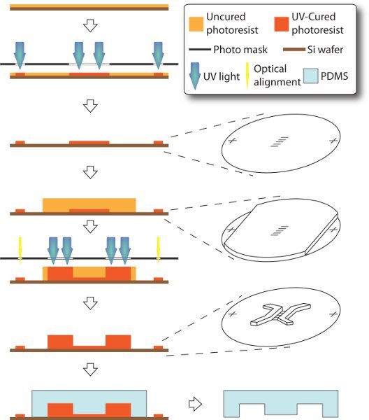
Figure 1. Schematics of fabrication of microfluidic device. The entire process is carried on a 3-inch silicon handle wafer through a modified technique of soft lithography. 3-μm-tall microchannels and alignment markers are made as in the first layer. Then 250-μm-thick su-8 is spin-coated, while the alignment markers are covered with scotch tape, such that they can later be accessible to mask aligner without sight-blocking by thick photoresist. Thus, chamber features can be made as the second layer and accurately aligned to the first layer. PDMS stamp is eventually molded off the resulting master.
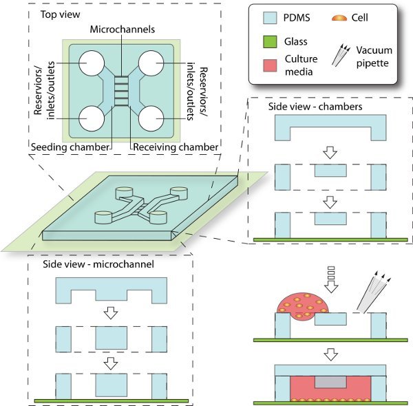
Figure 2. Schematics of device assembly and cell seeding process. Enclosed by PDMS and glass coverslip, the 3D culturing space is composed of chambers, reservoirs and microchannels. The seeding chamber is filled with cell culture, while the receiving chamber is initially filled with cell-free media. The microchannels that connect between them provide cell migrating trail from seeding side to receiving side.
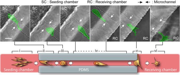
Figure 3. BTSC migration through microchannel. Upper: snapshots of time-lapse show a single cell (highlighted in green) migrates over 400 μm from the seeding side to the receiving side. The entire journey takes about 2 days, involving a sequence of cell morphological changes. The scale bar is 40 μm. Lower: a cartoon representation of six migration stages. Pre-migration (i): In seeding chamber, spindle-shaped and dividable cells gradually migrate along each other. The cells near microchannel entrance race with each other by polarizing cell body and exerting lamellipodia protrusion. Initiation (ii): The migratory cell with the highest capacity occupies the channel entrance while its competitors will retreat. Path-exploration (iii): The migratory cell changes to an amoeboid mode with little polarity. This migration mode is extremely motile and able to explore path in all directions by blebbing small membrane protrusions. Cruising (iv): Once the migration path is determined, the cell transforms into an adapted amoeboid mode by maintaining an additional large protrusion heading forward. This way, cell upholds a high motility as well as a steady direction and speed. Destination-exploration (v): Upon path-end, the cell slows down and develops filopodias to explore the receiving chamber for any invasion target. Post-migration (vi): After entering the receiving chamber, cell turns into star-shaped and retains high motility but no determined direction.
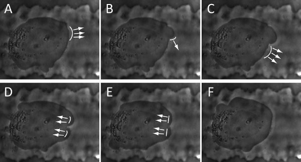
Figure 4. Snapshots of time-lapse show the cycle of blebbing activity and membrane deformation of a BTSC: (A-B). initiation; (B-D). Expansion; (D-F). Retraction. The arrows and curve-lines represent the direction and location of membrane deformation, respectively. The snapshots are collected every 8 seconds.
Discussion
The microfluidic device and image-recording technique presented here enables a visual characterization of cellular morphology during migration. Compared to existing conventional methods, the microfluidic platform features advantages of cost-effectiveness, high throughput and design flexibility. The presented microscopic visualization system permits study and recording of long-term live cell migration. The lens-motorized feature makes it possible to track multiple migration paths in a high image-resolution without disturbing the sample.
During assembly of the device, the PDMS stamp is non-permanently bonded to the glass coverslip for the convenience of PDL coating (step 3.4). It is critical to achieve a good seal for the success of this protocol. Contamination introduced from the device fabrication, such as air bubble in the stamp or dust/debris on the substrate, can jeopardize the bonding and result in fluid leaking. Therefore, treating the device in a dust-free manner is important to prevent device failure. Prior to the PDL-coating, the glass coverslips are nitric acid treated and the PDL solution is centrifuged to eliminate dust/debris. We find Scotch tape, alcohol rinse, and water bath very helpful in removing dust/debris from the PDMS stamp, if a clean room is not accessible. After the PDMS stamp making contact with the glass coverslip, tapping the stamp gently with tweezers facilitates the seal.
BTSCs can be enriched from human operating room specimens via sphere culture in stem cell medium, similar to culture of normal neural stem cells10. BTSCs enriched in this manner demonstrate stem cell-like properties, such as expression of stem cell markers (CD133, nestin), differentiation to multiple neural lineages (glial and neuronal), and tumor initiation in an orthotopic immunodeficient mouse model with as few as 100 cells18. Although some debate exists about purification and maintenance of BTSCs1, 19-21, sphere-grown BTSCs better maintain the phenotype and genotype of the parental tumor22-24.
The compartmentalized space mimics the physiological environment for cell migration. In our device, BTSC exhibit a strong capacity of migration through a size-constrained space by regulating cellular morphology. Our characterization of the cell morphological changes indicates mode-transformations in a six stage sequence that may model a possible new detailed description of BTSC invasion of adjacent brain. In early stages, the cells gain a significant amount of polarity and generate adhesive protrusions to effectively anchor themselves inside the microchannel. Once the cell occupancy in the microchannel is established, it converts to a cruising mode and maintains this mode for the entire journey through a microchannel. At this stage, BTSC maintain high motility and consistent direction but conserve energy. Interestingly, it appears that one microchannel is restricted to one cruising cell at a time, such that when a single cell proceeds to this stage, other cells retreat from the microchannel. This mechanism likely ensures effectiveness of tumor spreading and prevents overconsumption of nutrients in microchannel. After completing migration across the microchannel, a cell regains its propensity for multidirectional protrusions and further exploration for invasion targets or new migration paths. The compartmentalizing microfluidic device offers a novel in vitro means of creating a microenvironment for studying BTSC infiltration of brain parenchyma.
This method can easily be adapted to the study of cancer stem cell (CSC) and migratory cell lines derived from other tumor types. Culturing cells in the microfluidic device can be performed in any modern biology laboratory that is equipped with an incubator and tissue culture expertise. Equipped with a su-8 master, PDMS casting and device assembly are feasible with some fundamental training in soft lithography. In addition, this platform may also be extended for other applications with integrating other functional modules such as gradient mixer, surface patterning, fluid control and microelectrode.
Disclosures
No conflicts of interest declared.
Acknowledgements
PAC is partially supported by a NIH T32 grant to University of Wisconsin Stem Cell Training Program (P. A. Clark). JSK was partially supported by the HEADRUSH Brain Tumor Research Professorship, Roger Loff Memorial GBM Research Fund, and the UW Foundation/ Neurosurgery Brain Tumor Research and Education Fund. JCW and YH are partially supported by NIH grant NIBIB 1R01EB009103-01.
Materials
| Name | Company | Catalog Number | Comments |
| Dulbecco’s modified eagle’s medium (DMEM), high glucose | GIBCO, by Life Technologies | 11965 | Brain tumor stem cell (BTSC) culture supplies |
| Ham’s F12 | GIBCO, by Life Technologies | 31765 | Brain tumor stem cell (BTSC) culture supplies |
| B27 supplement minus vitamin A | GIBCO, by Life Technologies | 12587-010 | Brain tumor stem cell (BTSC) culture supplies |
| Antibiotic-Antimycotic (PSA) | GIBCO, by Life Technologies | 15240 | Brain tumor stem cell (BTSC) culture supplies |
| Epidermal Growth Factor (EGF), human recombinant | GIBCO, by Life Technologies | PHG0313 | Brain tumor stem cell (BTSC) culture supplies |
| basic Fibroblast Growth Factor (bFGF) , human recombinant | GIBCO, by Life Technologies | PHG0021 | Brain tumor stem cell (BTSC) culture supplies |
| Heparin sodium salt, from porcine intestinal mucosa | Sigma-Aldrich | H1027-250KU | Brain tumor stem cell (BTSC) culture supplies |
| Laminin (natural mouse) | GIBCO, by Life Technologies | 23017-015 | Brain tumor stem cell (BTSC) culture supplies |
| Accutase | EMD Millipore | SCR005 | Brain tumor stem cell (BTSC) culture supplies |
| Stem cell medium |
| ||
| Basic Fibroblast Growth Factor (bFGF)/ Heparin |
| ||
| Epidermal Growth Factor (EGF) |
| ||
| Heparin |
| ||
| su-8 photoresist | MicroChem Corp. | ||
| Silicon handle wafer | WRS Materials | 3P01-5SSP-INV | |
| trichloro(1H,1H,2H,2H-perfluorooctyl)silane | Sigma-Aldrich | 448931 | |
| PDMS Sylgard 184 | Dow Corning | ||
| laminin | BD Biosciences | 50 μg/ml in PBS buffer for the final concentration | |
| Biostation IM | Nikon Instruments |
References
- Carke, M. F. Cancer Stem Cells-Perspectives on Current Status and Future Directions. AACR Workshop on Cancer Stem Cells. Cancer Research. 66, 9339-9344 (2006).
- Stupp, R. Radiotherapy plus concomitant and adjuvant temozolomide for glioblastoma. New England Journal of Medicine. 352, 987-996 (2005).
- Sahai, E. Mechanisms of cancer cell invasion. Current Opinion in Genetics & Development. 15, 87-96 (2005).
- Shackleton, M., Quintana, E., Fearon, E. R., Morrison, S. J. Heterogeneity in Cancer: Cancer Stem Cells versus Clonal Evolution. Cell. 138, 822-829 (2009).
- Karnoub, A. E. Mesenchymal stem cells within tumour stroma promote breast cancer metastasis. Nature. 449, 557-557 (2007).
- Huang, Y., Agrawal, B., Sun, D., Kuo, J. S., Williams, J. C. Microfluidics-based Devices: New Tools for Studying Cancer and Cancer Stem Cell Migration. Biomicrofluidics. 5, (2011).
- Rolli, C. G., Seufferlein, T., Kemkemer, R., Spatz, J. P. Impact of Tumor Cell Cytoskeleton Organization on Invasiveness and Migration: A Microchannel-Based Approach. Plos One. 5, (2010).
- Chung, S. Cell migration into scaffolds under co-culture conditions in a microfluidic platform. Lab on a Chip. 9, 269-275 (2009).
- Irimia, D., Toner, M. Spontaneous migration of cancer cells under conditions of mechanical confinement.Integrative Biology. 1, 506-512 (2009).
- Svendsen, C. N. A new method for the rapid and long term growth of human neural precursor cells.Journal of Neuroscience Methods. 85, 141-152 (1998).
- Clark, P. A. Glioblastoma cancer stem cells exhibit decreased dependence on exogenous growth factors for proliferation and survival. Forthcoming Forthcoming.
- Xia, Y. N., Whitesides, G. M. Soft lithography. Angewandte Chemie-International Edition. 37, 551-575 (1998).
- Millet, L. J., Stewart, M. E., Sweedler, J. V., Nuzzo, R. G., Gillette, M. U. Microfluidic devices for culturing primary mammalian neurons at low densities. Lab on a Chip. 7, 987-994 (2007).
- Regehr, K. J. Biological implications of polydimethylsiloxane-based microfluidic cell culture. Lab on a Chip. 9, 2132-2139 (2009).
- Dent, E. W. Filopodia are required for cortical neurite initiation. Nature Cell Biology. 9, 1347-1347 (2007).
- Hu, X. D., Viesselmann, C., Nam, S., Merriam, E., Dent, E. W. Activity-Dependent Dynamic Microtubule Invasion of Dendritic Spines. Journal of Neuroscience. 28, 13094-13105 (2008).
- Vitzthum, L. Study of Na(+)/H(+) exchange-mediated pH(i) regulations in neuronal soma and neurites in compartmentalized microfluidic devices. Integrative Biology. 2, 58-64 (2010).
- Clark, P. A., Treisman, D. M., Ebben, J., Kuo, J. S. Developmental signaling pathways in brain tumor-derived stem-like cells. Developmental Dynamics. 236, 3297-3308 (2007).
- Chen, R. H. A Hierarchy of Self-Renewing Tumor-Initiating Cell Types in Glioblastoma. Cancer Cell. 17, 362-375 (2010).
- Pollard, S. M. Glioma Stem Cell Lines Expanded in Adherent Culture Have Tumor-Specific Phenotypes and Are Suitable for Chemical and Genetic Screens. Cell Stem Cell. 4, 568-580 (2009).
- Lobo, N. A., Shimono, Y., Qian, D., Clarke, M. F. The biology of cancer stem cells. Annual Review of Cell and Developmental Biology. 23, 675-699 (2007).
- Singh, S. K. Identification of human brain tumour initiating cells. Nature. 432, 396-401 (2004).
- Lee, J. Tumor stem cells derived from glioblastomas cultured in bFGF and EGF more closely mirror the phenotype and genotype of primary tumors than do serum-cultured cell lines. Cancer Cell. 9, 391-403 (2006).
- Galli, R. Isolation and characterization of tumorigenic, stem-like neural precursors from human glioblastoma. Cancer Research. 64, 7011-7021 (2004).